It all began one summer afternoon in Ellensburg. The proud owner of an RCA model 29K radio walked in my shop and asked if I repaired old radios. "Do I repair old radios?" I replied, "With loving care!"
There is some confusion since the name of my electronics shop
has been Current Products Repair since 1984. It's only been recently
that I decided to cut down on repair of modern consumer electronics and
concentrate on older, vacuum tube models. (Which, by the way, still do use electric current) Most of what is manufactured
today, or in the last 15 years, is manufactured with the intent to be thrown
away in the case of failure. That does not fare well for those of us repair techs
that like to keep things running. I'm doing my part to prevent entropy. And rather that changing my name to Not So Current Products Repair, I decided on Welcome Back Radio.
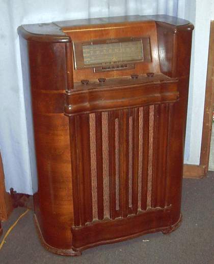
So Larry went back to his truck and brought in a
beautifully crafted radio, wonderfully weathered with years of use and home to a few
spiders. The only visible damage was the power transformer hanging loose out of
the chassis. He said he was sure that's all that was wrong. "It
worked fine before the transformer started leaking oil then eventually
failed," he said with confidence, "It sure does pull in the stations
like nothing else!" I told him I'd look it over and get back to him with a
quote.
The first thing I did was make sure I could locate a
replacement transformer. The schematic was no problem, the transformer a little
more difficult. I e-mailed a fellow repair shop owner named Dennis in Florida who said he had two that would work. An original RCA part that would
fit right in the chassis but with higher voltage ratings, and a part with
proper voltage ratings that I'd have to jerry-rig to mount. I opted for the
one that fit and would just get higher rated filter capacitors to handle the increased voltages.
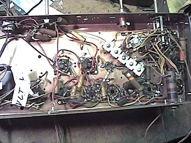
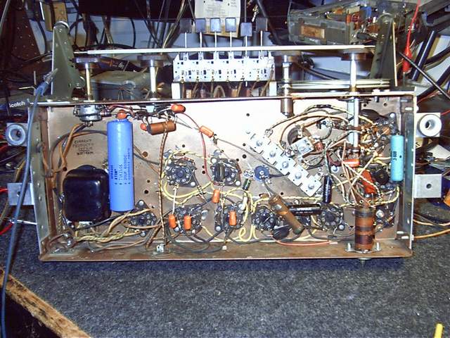
After testing all the tubes, most were OK with exception of three. I had Dennis include these in the order with the transformer. About this time I was shopping for a digital camera, so I took a shot of the underside of the chassis with a cheap cam (that I ended up taking back.) You can see (though the photo is poor) that the transformer had arrived. Once I attempted wiring it I discovered the existing wiring was going to need to be replaced. The insulation had been heated so much over years of use that it would crumble off the copper wire simply by touching it. (Click your "Back" button to return here.) see photo
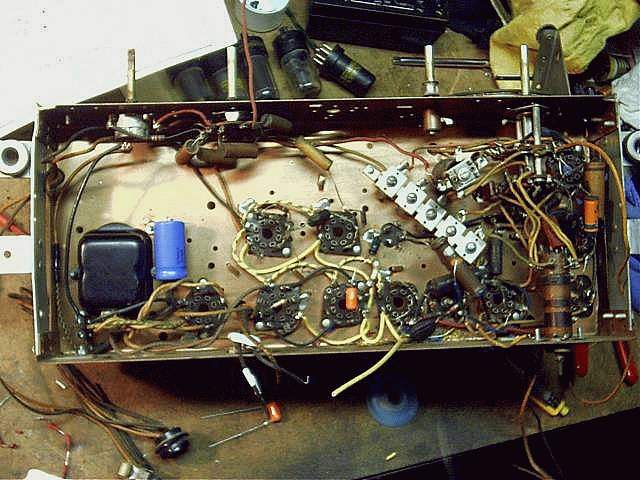
The old wiring was solid copper with rubber or plastic insulation. I decided to use all cloth insulated, stranded wire so it would last longer than it already had. By this time I had chosen a Pentax EI-100 digital camera. You can see that it takes a lot better quality picture. I started re-wiring from the left. see photo
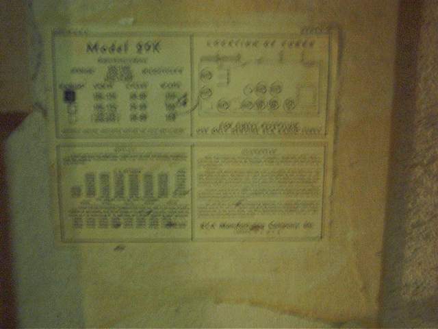
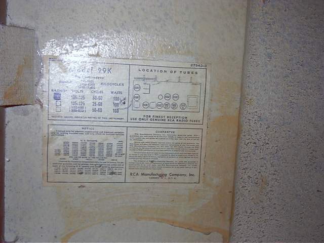
One thing you don’t see anymore is manufacturers including technical information intended for a service tech right inside the unit. And you can see I'm still a little shaky with my new camera. see photo I’ve got the distinct impression that most companies today prefer it if nobody can repair their product.
As I progressed with the laborious task of replacing all the wiring, the schematic was helpful only to a point. I needed to draw out a chassis wiring diagram as I removed the existing wires because wire placement and routing is important. see photo
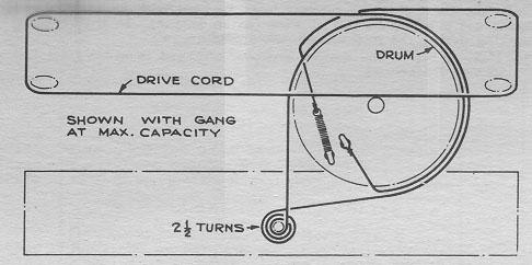
The schematic I acquired did not have a diagram for restringing the dial cord, and it was not intact when I got the radio, so I found this one on the internet. (The transformer is the only thing broken on it, yeah right!) dial cord diagram for RCA 29K
I also replaced nearly all of the paper capacitors with Sprague Orange Drop Polypropylenes. It took more than a few late nights without distraction to finish the wiring, but it sure looks pretty with all that cloth covered wiring and shiny caps. wiring completed! Time to power her up.
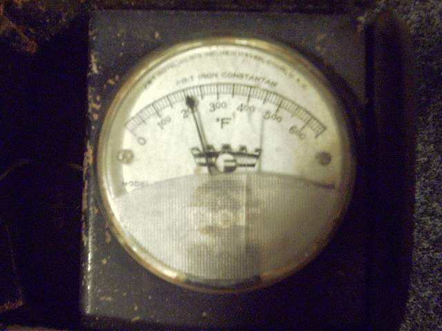
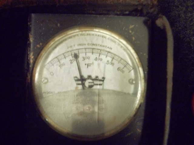
I upgraded the main filter capacitors from 400 volt to 500 volt on the first and 450 volt on the second thinking that would be enough. I was wrong. When the unit is first powered up, before the tubes warmed up, the first cap was seeing 900 volts and the second around 600. The 500 volt withheld but 450V didn’t. I ended up using 600V caps for both. As I was troubleshooting this I noticed the transformer was getting a little hot. I read this as 200 F. I’d better keep an eye on that.
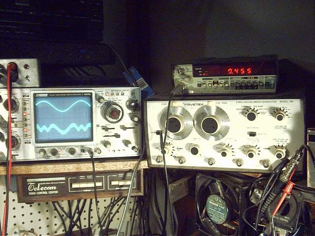
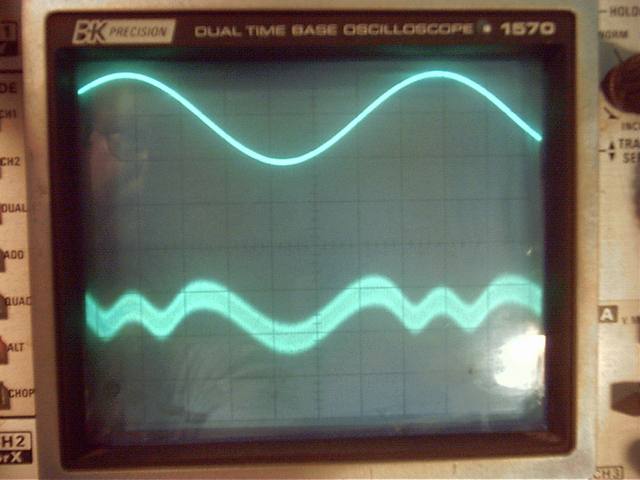
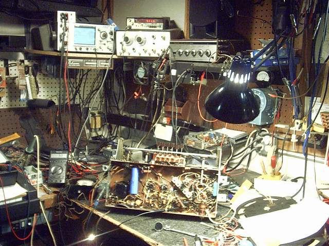
Time to subject it to my test gear and see if I can get it to vibrate at the proper frequencies (they call that oscillate in technical circles.) And this is my Oscilloscope and frequency generator: photo
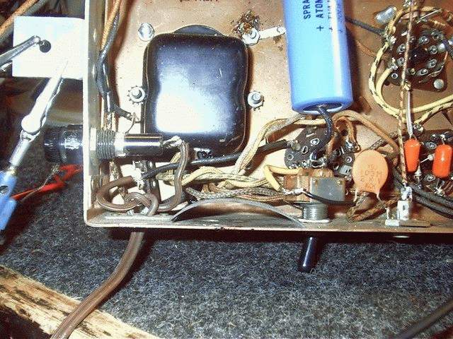
Meanwhile, since I was switching it on and off so much while aligning, I decided to put a “standby” switch, basically to keep the high voltage from hitting the circuits until the filaments had warmed up. This was not only to extend the life of the capacitors, but is much easier on the plates of the tubes as well. see photo I figured a fuse would be appropriate since that transformer was getting even hotter. 200F+ (for reference, the tubes typically run about 180F.) I was estimating at this point that RCA had underestimated the current capacity of the stock transformer in the original design, and this is why the first one hadn’t lasted. (I was wishing I would have forseen this and gone with a non-stock beefier one at this point.)
Aligning a superhetrodyne receiver is a tedious process. If you are technical and/or interested, here is a good article on the typical procedure for a TRF (Tuned Radio Frequency) set. TRF Alignment procedure If you are not as technically inclined you may prefer to read the article I wrote on the Seattle Mariners radio broadcaster Dave Niehaus while I was aligning this RCA. Was that good hitting, or just bad pitching?
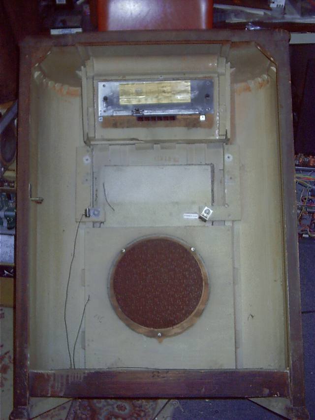
Here is the final tweek. photo At this point I needed a little more coffee. Things were not quite as shaky on the oscilloscope and the enclosure was all ready to receive the newly wired and aligned chassis. But not before one more check of all the details.
I phoned Larry and let him know it would be ready and he was at my shop within an hour. (It’s about a 20 minute drive from upper county.) He was so anxious to get it home and plugged in that it was difficult to spend some time going over the new options. (i.e. fuse location and type, standby switch operation, I showed him he shouldn’t turn up the bass too much because the cabinet had some loose boards that rattled, he had told me not to do anything with the cabinet.) He had it in the back of his pickup truck before I realized I hadn’t had a chance to photograph the chassis installed in the cabinet. You’ll just have to go back to the enclosure picture above and imagine it with me.
It sounded almost as good as it looks and almost as good as the sound of his check paying the rent for that month. Thanks Larry, I enjoyed restoring it probably as much as you are enjoying listening to it.
Return to WBRadio Home